Bitbots Lowlevel
What do the low level packages do?
The low level packages are responsible for the robot’s motion. The different hardware and software components used are described in this article. Additionally, common problems and troubleshooting strategies are explained.
The behavior of the low level packages is dominated by the control loop, i.e. the cycle that alternately reads and writes motor positions. In parallel to this cycle, the new positions are calculated based on observed values.
To react to problems as fast as possible, e.g. overload errors in the motors, a faster control loop is desirable. Formerly, our loop ran with a frequency of 100Hz, therefore the reaction time to errors is at least 20ms because the error has to be read, processed and written, which takes at least two cycles.
There are essentially three possibilities to accelerate the control loop:
Send the bits faster over the bus, but this is limited by the baud rate of up to four megabaud (Robotis claims to achieve 4.5 MBaud, but we were not able to reproduce this)
Compress the data, e.g. by using special commands to read multiple motors at once (sync read and sync write)
Use more buses, in our case, one bus per limb would make sense
Since we cannot increase the baud rate due to these limitations, our code only utilizes the second and third points.
How is the hardware control structured?
Motors and Buses
The lowest end of the hardware control are the motors. We use Dynamixel motors MX-106 and MX-64, as well as the XH540 by Robotis. The motors are connected by the motorbus using RS-485 or TTL.
The cables for RS-485 consist of four wires, two of which are ground and VCC (14.8 to 16.8 V, depending on the current battery voltage), one for data (5V) and one for the inverted data. When crimping new cables or when connecting a logic analyzer, it is important to not interchange the data and VCC cables because the motors are damaged when there are more than 5V on the data bus.
The cables for TTL only have three wires: Ground, VCC and data. For the correct crimping, the same as for the RS-485 cables applies.
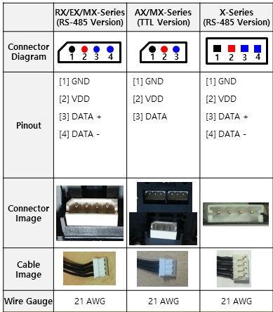
This figure shows the pinouts of the different connectors we use. When crimping new cables, it is important to follow this scheme.
The communication with the motors happens via the Dynamixel Bus Protocol. Details are documented in their protocol specification. We are using protocol Version 2, but protocol Version 1 can be used as a reference as well.
A message of the protocol essentially consists of a header, the goal motor id, an instruction, a parameter list and a check sum. The most important instructions are ping, read, write and status as well as sync read and sync write to read/write multiple motors at once.
Every motor has a fixed id by which it can be addressed. The id of a new / reset motor is 1 but can be changed using a write instruction to a special register. We can do this for example using the dynamixel wizard. A reference to the ids we use in our robot can be found here: Servo numbers
Two motors with the same id should not be connected to the same bus because of the resulting communication problems.
On a sync read, the motors answer in the order by which they are addressed in the sync read. When one of the motors does not answer, the following motors will also not answer because they wait for the previous motor.
CORE Board
The CORE Board is connected to the NUC via USB and to the motors via the four motor busses. It takes care of the communication between the NUC and the motors by reading message from the bus and redirecting them to the NUC and vice versa. The IMU is also located on the bus and its values are treated the same as the motor values.
Kernel
You should adjust the latency timer value. For the version Ubuntu 16.04.2 and later, the default latency timer of the usb serial is ‘16 msec’. When you are going to use sync / bulk read, the latency timer should be loosen. The lower latency timer value, the faster communication speed.
You can check its value by:
$ cat /sys/bus/usb-serial/devices/ttyUSB0/latency_timer
If you think that the communication is too slow, type the following after plugging the usb in to change the latency timer
Method 1. Type the following (you should do this everytime when the usb was plugged out or the connection was dropped)
$ echo 1 | sudo tee /sys/bus/usb-serial/devices/ttyUSB0/latency_timer
$ cat /sys/bus/usb-serial/devices/ttyUSB0/latency_timer
Method 2. If you want to set it to be done automatically, and don’t want to do the above everytime, make rules file in /etc/udev/rules.d/. For example,
$ echo ACTION==\"add\", SUBSYSTEM==\"usb-serial\", DRIVER==\"ftdi_sio\", ATTR{latency_timer}=\"1\" > 99-dynamixelsdk-usb.rules
$ sudo cp ./99-dynamixelsdk-usb.rules /etc/udev/rules.d/
$ sudo udevadm control --reload-rules
$ sudo udevadm trigger --action=add
$ cat /sys/bus/usb-serial/devices/ttyUSB0/latency_timer
If you have another good idea that can be an alternative, Robotis is asking for advice via a Github issue: https://github.com/ROBOTIS-GIT/DynamixelSDK/issues
Dynamixel SDK
The Dynamixel SDK implements the Dynamixel protocol. It provides methods to send instructions and to read status packets in different programming languages. We use a fork of Robotis’ Dynamixel SDK because Robotis did not implement the sync read on multiple registers.
Dynamixel Workbench
The Dynamixel Workbench provides higher level functions than the Dynamixel SDK. For example, the motor positions in the SDK are given as values between 0 and 4096 (2 Byte) which is converted to radians by the Dynamixel Workbench. Thereby, the Workbench eases the work with the motors on a more abstract level. We use a fork which specifies our custom devices.
ROS Control Framework
The ROS Control Framework is a part of ROS that is responsible for the motor and sensor control. There are controllers for ROS Control that provide the interface between ROS and low level software parts. These controllers are hardware agnostic because they are using interfaces to abstract from the hardware (e.g. motors). To control the motors, the Dynamixel Controller is used, which itself uses the Dynamixel Hardware Interface.
ROS messages
After all these steps we’re finally at the ROS message level. There are two message types handled here: The joint state message gives the current positions of the motors, while the joint goals message can specify target positions for motors. The hardware interface also manages the IMU data and the values returned by the foot sensors.
How do we use bitbots_ros_control?
The package bitbots_ros_control provides the hardware interface for the dynamixel motors.
The most important configuration file for this is the wolfgang.yaml. In this file you find multiple settings for defining, which values should be read from the motors (temperature, speed, force, …), which sensors should be used (foot pressure sensors, IMU) and which settings should be set (control loop frequency, baud rate, CORE ports, auto torque, …).
The corresponding ROS node can be launched with roslaunch bitbots_ros_control ros_control.launch. This will execute the following steps:
The motors are pinged in alphabetical order. This happens due to the way yaml files are read. This means the HeadPan motor (id 19) is read first, while the RShoulderRoll motor (id 3) is read last.
The values from the config file are written into the RAM and ROM of the motors. These are values like speed or return delay time.
The message “Hardware interface init finished” is printed to the terminal.
The control loop starts, alternating between sync read and sync write.
The controllers for ROS control are loaded.
Help, I have a problem!
Error Opening Serial Port
If you encounter the message “Error opening serial port”, no connection between the NUC and the CORE board could be established. Therefore your first instinct should be checking whether the cable is plugged in correctly. If this does not solve the problem, you can check whether the board can be found by using lsusb (look for the “leaf” entry). You can further investigate this by using ls /dev/. You should find the devices “/dev/ttyUSB0” through “/dev/ttyUSB3”, one for each of the four busses. If the names are different, you may have to alter the wolfgang.yaml file or unplug the CORE board and plug it back in, in order to make it use the known names.
Motor problems
The first thing you should do if you have a motor problem (“no status from id”, motors stuttering, …) is checking whether all cables are plugged in correctly, starting with the cables that are near the affected motor. Sometimes one of the cable sits loosely in its socket and may fall out entirely when the robot moves. To control whether all motors are reachable, this software by Robotis can be used. Next you should check whether the update rate is significantly lower than the usual 700 Hz. A very low update rate may cause the motors to be unreachable.
If the problem persists, you can investigate it further by using a logic analyzer to find bus errors. The logic analyzer is a little black box with a lot of coloured wires ( like this). With this tool you can read the data from up to 16 busses at a time. To do so, plug the ground cable into the ground of the bus and one of the coloured cables into one of the data wires. It is very important not to confuse these two cables, as this may cause serious damage to the motors or the analyzer.
By using the software Saleae Logic, the data can be recorded and read. To do so, you have to select 15MB/s and a voltage of 5V via the button next to the start button. Next you can start the recording and then start the problematic program. Now the Async Serial Analyzer can be used to show the bytes of the messages, which can be decoded using the protocols linked above, or install the dynamixel analyzer plugin provided here <https://github.com/r3n33/SaleaeDynamixelAnalyzer.
Another source for the problem could be the CORE board. You can check the CORE board for errors using the following methods:
Try running the same software on a different robot with a different CORE board.
Replace the CORE board on the same robot to see if the NUC is working properly.
Use Wireshark on the interface from the NUC to the CORE (/dev/ttyUSBX) to make sure the communication on the bus is forwarded properly to the NUC
If the error still can not be found, some higher level software has to be responsible. You should check whether an update for the DynamixelSDK or Dynamixel Workbench is available. If this does not fix the problem, you have to debug these packages manually.