Bitbots IMU DXL Module
|
|
|
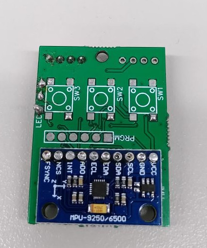
IMU without buttons
and LEDs (top side)
|
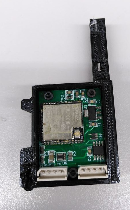
IMU in 3d printed case
with RS485 connectors
(bottom side)
|
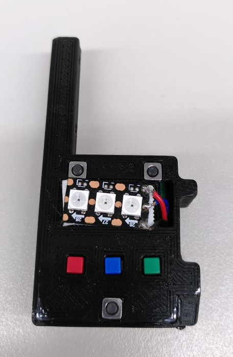
IMU in 3d printed case
with buttons and LEDs
(top side)
|
Features
12 Bit 3 axis gyroscope and 3 axis accelerometer (MPU6500 sensor)
1000 Hz update rate
configurable range (250-2000 deg/sec and 2-16g)
configurable onboard complementary filter
gyroscope and accelerometer calibration procedure
direct reading of orientation as quaternion
connection via the Dynamixel bus
WS2812b RGB LEDs
3 Buttons
Software
The software consists of two parts. Firstly the firmware which is installed on the ESP32 and secondly (at least for us) the ros_control based diver to communicate with the board. You can communicate to the board using the standard Dynamixel protocol version 2.0, if you wish to write your own hardware interface for it. Version 1 may also work, but we did not test it.
Firmware
The firmware is uses the Arduino framework. We usually install it using the Arduino IDE. The required libraries are:
MPU9250/MPU6500 on branch MPU6500
For installing the build tools for the ESP32 refer to espressif’s documentation.
For flashing a ESP32 Wroom (without development board) we recommend a programming socket.
If the board is already soldered, the programming header can be used. The square pin is pin 1 (+3V3). Please refer to the schematic for the pinout. There is a known issue with this.
ROS Control
We developed a hardware interface that complies with the ros_control standard for the Wolfgang robot platform. This includes a hardware interface for the IMU. Documentation for it can be found here: Bitbots Lowlevel
Known Issues
The ESP32’s UART1 is connected to the Dynamixel bus. It is also normally used for programming. If the level shifter (U4) is installed, programming is not possible even with the programming header.
Soldering the MPU6500 module on the IMU module is quite difficult. We have used hot air and destroyed some modules with it.
RS485/TTL selection
R1 and R2 should not be populated, if RS485 is used to communicate with the board. They must be installed, if TTL is used.
Register Table
Adress |
Length |
Name |
Access |
Default |
Type |
Persistent |
|---|---|---|---|---|---|---|
7 |
1 |
rw |
241 |
int8 |
yes |
|
8 |
1 |
rw |
4 |
int8 |
yes |
|
10 |
4 |
rw |
0 |
int8[4] |
no |
|
14 |
4 |
rw |
0 |
int8[4] |
no |
|
18 |
4 |
rw |
0 |
int8[4] |
no |
|
36 |
4 |
r |
float32 |
|||
40 |
4 |
r |
float32 |
|||
44 |
4 |
r |
float32 |
|||
48 |
4 |
r |
float32 |
|||
52 |
4 |
r |
float32 |
|||
56 |
4 |
r |
float32 |
|||
60 |
4 |
r |
float32 |
|||
64 |
4 |
r |
float32 |
|||
68 |
4 |
r |
float32 |
|||
72 |
4 |
r |
float32 |
|||
76 |
1 |
r |
int8 |
|||
77 |
1 |
r |
int8 |
|||
78 |
1 |
r |
int8 |
|||
102 |
1 |
rw |
3 |
int8 |
yes |
|
103 |
1 |
rw |
3 |
int8 |
yes |
|
104 |
1 |
rw |
0 |
int8 |
yes |
|
105 |
1 |
rw |
0 |
int8 |
yes |
|
106 |
1 |
rw |
0 |
int8 |
yes |
|
107 |
1 |
rw |
0 |
int8 |
yes |
|
108 |
1 |
rw |
0 |
int8 |
yes |
|
109 |
1 |
rw |
0 |
int8 |
yes |
|
110 |
4 |
rw |
0.04 |
float32 |
yes |
|
114 |
4 |
rw |
0.01 |
float32 |
yes |
|
118 |
4 |
rw |
7.5 |
float32 |
yes |
|
122 |
4 |
rw |
0.0 |
float32 |
yes |
|
126 |
4 |
rw |
0.0 |
float32 |
yes |
|
130 |
4 |
rw |
0.0 |
float32 |
yes |
|
134 |
4 |
rw |
1.0 |
float32 |
yes |
|
138 |
4 |
rw |
1.0 |
float32 |
yes |
|
142 |
4 |
rw |
1.0 |
float32 |
yes |
DXL
id: Can be a value between 1 and 252. It is used to talk to the device over the Dynamixel bus.
baud: Can be a value between 0 and 7
value |
baud |
Tested |
|---|---|---|
0 |
9,600 |
no |
1 |
57,600 |
no |
2 |
115,200 |
no |
3 |
1M |
no |
4 |
2M |
yes |
5 |
3M |
no |
6 |
4M |
yes |
7 |
4.5M |
no |
We are reasonably certain that the other baud rates work as well, since the ESP32 supports them.
LEDs
led{0,1,2}: Byte order: RGB, 4th byte is ignored but reserved.
IMU
gyro_{x,y,z}: Current measurement of the gyroscope in the respective axis in rad/s
accel_{x,y,z}: Current measurement of the accelerometer in the respective axis in m/s^2
quaternion_{x,y,z,w}: Quaternion giving the orientation of the imu in respect to to ground.
Ranges
gyro_range: Can be a value between 0 and 3
value |
range |
|---|---|
0 |
±250 deg/s |
1 |
±500 deg/s |
2 |
±1000 deg/s |
3 |
±2000 deg/s |
accel_range: Can be a value between 0 and 3
value |
range |
|---|---|
0 |
±2 g |
1 |
±4 g |
2 |
±8 g |
3 |
±16 g |
IMU calibration
calibrate_gyro: Setting this value to 1 causes the gyroscope to be calibrated, the module is unresponsive for around 2 seconds This procedure should be performed when the IMU is not moving. It should be done relatively frequently. The gyro calibration is not persistent.
reset_gyro_calibration: Resets the gyro calibration. Useful, if the gyro was accidentally calibrated while moving.
calibrate_accel: Starts the accelerometer calibration routine.
reset_accel_calibration: Resets the accelerometer calibration. Be careful as it can be tedious to perform the calibration routine.
accel_calibration_threshold: The threshold used for accelerometer accelerometer calibration.
accel_bias_{x,y,z}: The bias (i. e. the offset from 0) calculated in the calibration routine.
accel_scale_{x,y,z}: The scale factor calculated in the calibration routine. Should be relatively close to 1.0 after calibration.
Complementary Filter
do_adaptive_gain: If 1, the gain is adapted to be weighted more if the IMU is in a steady state.
do_bias_estimation: If 1, the bias of the gyroscope is estimated when the IMU is in a steady state.
accel_gain: How much the orientation is influenced by the accelerometer.
bias_alpha: In the bias estimation, how strongly the biases are adjusted if do_bias_estimation is 1 and the IMU is in a steady state.
Accelerometer Calibration
It is necessary to calibrate the accelerometer once before using it. For this, the accelerometer must be placed with the x,y, and z-axis pointing downwards and upwards once. We have designed the 3D printed case for the board in such a way, that this is relatively easy.
Before starting the calibration, you should check the accelerometer measurements. For each of the axes pointing downwards or upwards the value should be at least 7.5 m/s^2. If this is not the case, you need to lower the accel_calibration_threshold.
To perform the calibration procedure follow this procedure:
Place the IMU on one of the 6 sides
Set a 1 to the calibrate_accel register (
rosservice call /imu/calibrate_accel, if you are using our software)Wait until the IMU responds to reads again (or around 5 seconds)
Repeat for remaining 5 sides
After the procedure, you should check the values in the accel_scale and accel_bias registers. Scale should be really close to 1 and bias can, in our experience, deviate by 1-2 m/s^2.